LAB 6 - MAE4190 FAST ROBOTS
Welcome to lab 6 of fast robots! In this lab we will be implementing orientation PID control on our car. This lab will involve controlling the yaw of your robot using the IMU.
Prelab
The set up for my Bluetooth data transmission and debugging system is similar to lab 5. I created three commands for starting the orientation control, stopping the control over bluetooth, as well as sending the data respectively.
/*
        start PID orientation control
        */
        case START_ORIENT:

            success = robot_cmd.get_next_value(target_angle);
                if(!success)
                    return;
            success = robot_cmd.get_next_value(Kp);
                if(!success)
                    return;
            success = robot_cmd.get_next_value(Kd);
                if(!success)
                    return;
            success = robot_cmd.get_next_value(Ki);
                if(!success)
                    return;

            tindex = 0;
            integral = 0;
            prev_error = 0;
            prev_time = millis();
            prev_sensor_time = millis();
            start_orient = true;

            break;
/*
         * Allowing the car to be stopped via BLE
         */
        case STOP_ORIENT:

            start_orient = false;
            control_stop();

            Serial.println("PID stopped");

            break;
        /*
         * Send data of PID controls through BLE
         */
        case SEND_ORIENT_DATA:

            for (int tindex = 0; tindex < tindex_max; tindex++){

                tx_estring_value.clear();
                //send time data
                tx_estring_value.append((float)time_doc[tindex]);
                tx_estring_value.append(",");
                //send yaw data
                tx_estring_value.append((float)yaw_doc[tindex]);
                tx_estring_value.append(",");
                //send error
                tx_estring_value.append((float)error_doc[tindex]);
                tx_estring_value.append(",");
                //send PID input
                tx_estring_value.append((float)PID_doc[tindex]);
                tx_estring_value.append(",");
                //send motor input
                tx_estring_value.append((float)motor_input[tindex]);
                tx_estring_value.append(",");

                tx_characteristic_string.writeValue(tx_estring_value.c_str());

            }

            break;
The hard stop after BLE disconnects is done the same as Lab 5.
Although now the two motors will be operating in opposite directions, their motor input will be basically the same (aside from calibration for weaker motors), just implemented on different motor pins.
The python code receiving data is as follows:
time_array = []
yaw_array = []
error_array = []
PID_array = []
motor_array = []

def notifyBle(uuid, data):
    data = data.decode()
    parts = data.split(",")

    time_array.append(float(parts[0]))
    yaw_array.append(float(parts[1]))
    error_array.append(float(parts[2]))
    PID_array.append(float(parts[3]))
    motor_array.append(float(parts[4]))
    print(yaw_array)
    #print(motor_array)
    #print(PID_array)
    print(error_array)
ble.send_command(CMD.START_ORIENT, "90|1.5|1.5|0")
print("start orient")
time.sleep(20)

ble.send_command(CMD.STOP_ORIENT, "")
print("stopped orient")
time.sleep(2)

ble.send_command(CMD.SEND_ORIENT_DATA, "")
print("got yaw data")
time.sleep(20)
ble.stop_notify(ble.uuid['RX_STRING'])
This allows me to change the PID values and the reference target angle easily without updating the code on the Artemis board.
Lab Tasks
Digital Motion Processor (DMP)
As I discovered from previous labs, my gyroscope has a pretty significant drift. Hence, I need to use the digital motion processor (DMP) for sensor fusion to mitigate the individual drawbacks of each sensor.
The DMP is capable of error and drift correction by fusing readings from the ICM’s 3-axis gyroscope, 3-axis accelerometer, 3-axis magnetometer/compass. For our purposes we will mostly only be fusing the accelerometer and gyroscope readings.
The maximum rotational velocity that the gyroscope can read by default, according to specs documentaiton, is about 250 degrees per second. This is a little slow for fast adjustments, but is supplemented by the DMP as it uses 2000 degrees per second.
I followed the instructions for the DMP. This is the code that I added to my loop:
//DMP
icm_20948_DMP_data_t data;
myICM.readDMPdataFromFIFO(&data);

// Is valid data available?
if ((myICM.status == ICM_20948_Stat_Ok) || (myICM.status == ICM_20948_Stat_FIFOMoreDataAvail)) {
// We have asked for GRV data so we should receive Quat6
    if ((data.header & DMP_header_bitmap_Quat6) > 0) {
        double q1 = ((double)data.Quat6.Data.Q1) / 1073741824.0; // Convert to double. Divide by 2^30
        double q2 = ((double)data.Quat6.Data.Q2) / 1073741824.0; // Convert to double. Divide by 2^30
        double q3 = ((double)data.Quat6.Data.Q3) / 1073741824.0; // Convert to double. Divide by 2^30
To convert quaternion data into euler angles for yaw (reference from Example7):
double q0 = sqrt(1.0 - ((q1 * q1) + (q2 * q2) + (q3 * q3)));

double qw = q0; // See issue #145 - thank you @Gord1
double qx = q2;
double qy = q1;
double qz = -q3;

double t3 = +2.0 * (qw * qz + qx * qy);
double t4 = +1.0 - 2.0 * (qy * qy + qz * qz);
double curr_angle = atan2(t3, t4) * 180.0 / PI; //from radians to degrees
yaw_doc[tindex] = curr_angle;
The implementation of my PID controls is very similar to that in lab 5, with the code as follows:
PIDResult PID_calculation(float curr_yaw)
{

    unsigned long curr_time = millis();
    float dt = (curr_time - prev_time)/1000.0;
    prev_time = curr_time;

    //calculate error for proportional
    float curr_error = curr_yaw - target_angle;
    //calculate integral term
    integral += curr_error * dt;
    //anti-wind up
    integral = constrain(integral, -300, 300); //change this when Ki is decided
    //calculate derivative term
    derivative = (curr_error - prev_error)/dt;
    prev_error = curr_error;
    //calculate PID
    float u = Kp * curr_error + Ki * integral  + Kd * derivative;

    PIDResult r;
    r.u_r = u;
    r.error_r = curr_error;
    r.time_r = curr_time;
    return r;
}
However, I encountered some difficulties during my tuning process for each of the PID parameters. Firstly, I quickly discovered that my power for moving linearly is much lower than that required for turning. As seen in my lab 4, the turning for my car is extremely slow and often with a wide radius, even with wheels turning in opposite directions. I think this is mostly due to my motors being highly unbalanced, which was less pbvious while moving linearly, but becomes a big problem when one side of wheels cannot overpower the other to turn.
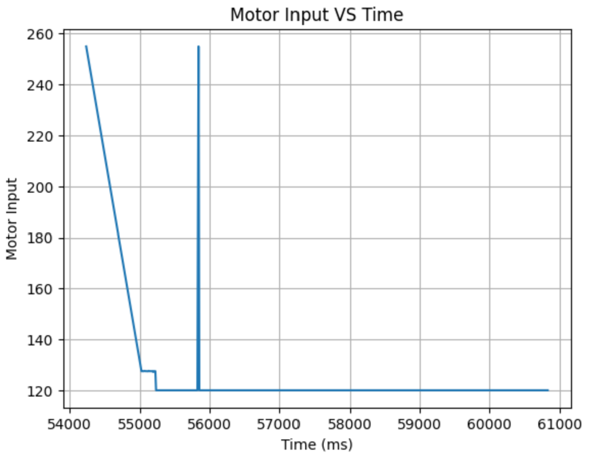
To mitigate the difference in motor capabilities, I had to bump up the ratio between the normal and adjusted speeds from 1.4 to 2.5. I also increased the lower limit of the weaker motor to 120 while keeping the other at the lowest that it could use to turn. The new motor control with PID input now looks like this:
void PID_forward(float PID_u, int i){

    float adj_speed = PID_u * 2.5; //adjusted for the weaker motor
    float norm_speed = PID_u;

    //make sure it doesn't go below the deadband or exceed the max PWM signal
    adj_speed = constrain(adj_speed, 120, 255);
    norm_speed = constrain(norm_speed, 70, 255);

    analogWrite(MOTOR1PIN1, 0);
    analogWrite(MOTOR2PIN1, norm_speed);
    analogWrite(MOTOR1PIN2, adj_speed);
    analogWrite(MOTOR2PIN2, 0);
    motor_input[i] = adj_speed;

}
I might need two different speed controls for driving and turning when we are to combine those two in the future.
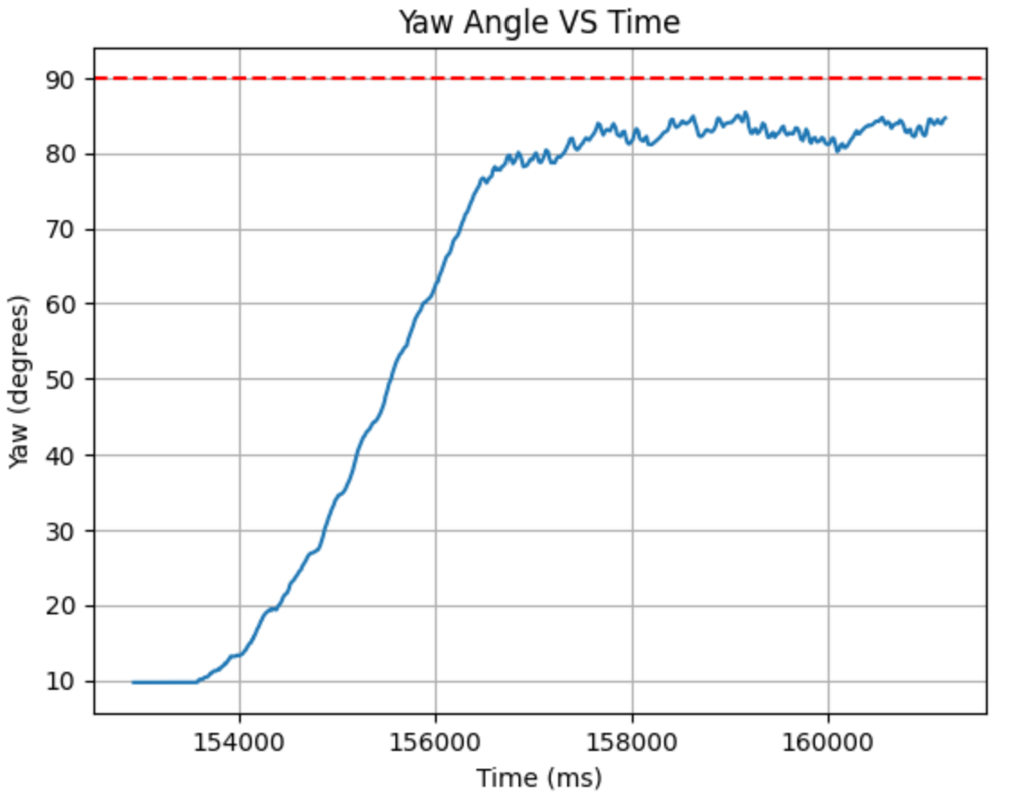
For proportional and derivative control, I took the values from my linear PID controller as a starting point. However, they were too weak for turning, so I gradually increased them until they could turn reliably, with Kp at 2.0 and Kd at 0.5. The Kd helped curb big oscillations and stopped overshoots, but there was a steady state error that remained:
Hence, I decided to add a Ki. I started with 0.00001. After more experimentation, I figured out that the Ki only helped to some extent, therefore it wasn’t quite the PID control giving it a steady state error, but the overpowering of one motor such that the other was not strong enough to correct it no matter how large the Ki. I changed the motor controls (as shown above) and set the Ki only to the max value that still had substantial effects in decreasing the error to avoid instabilities in setting it too high.
Final values: Kp: 2.2, Kd: 0.3 Ki: 0.0001
I had to lower the Kd value a little since, as seen in the video, the car does a big spin in the beginning. My initial derivative calculation may be very high due to the large difference in error while initializing over a relatively short amount of time. It also may be caused by the fact that the ‘starting’ velocity of the wheels to overcome friction is much higher that that needed when it begins to run, and hence it overshoots significantly.
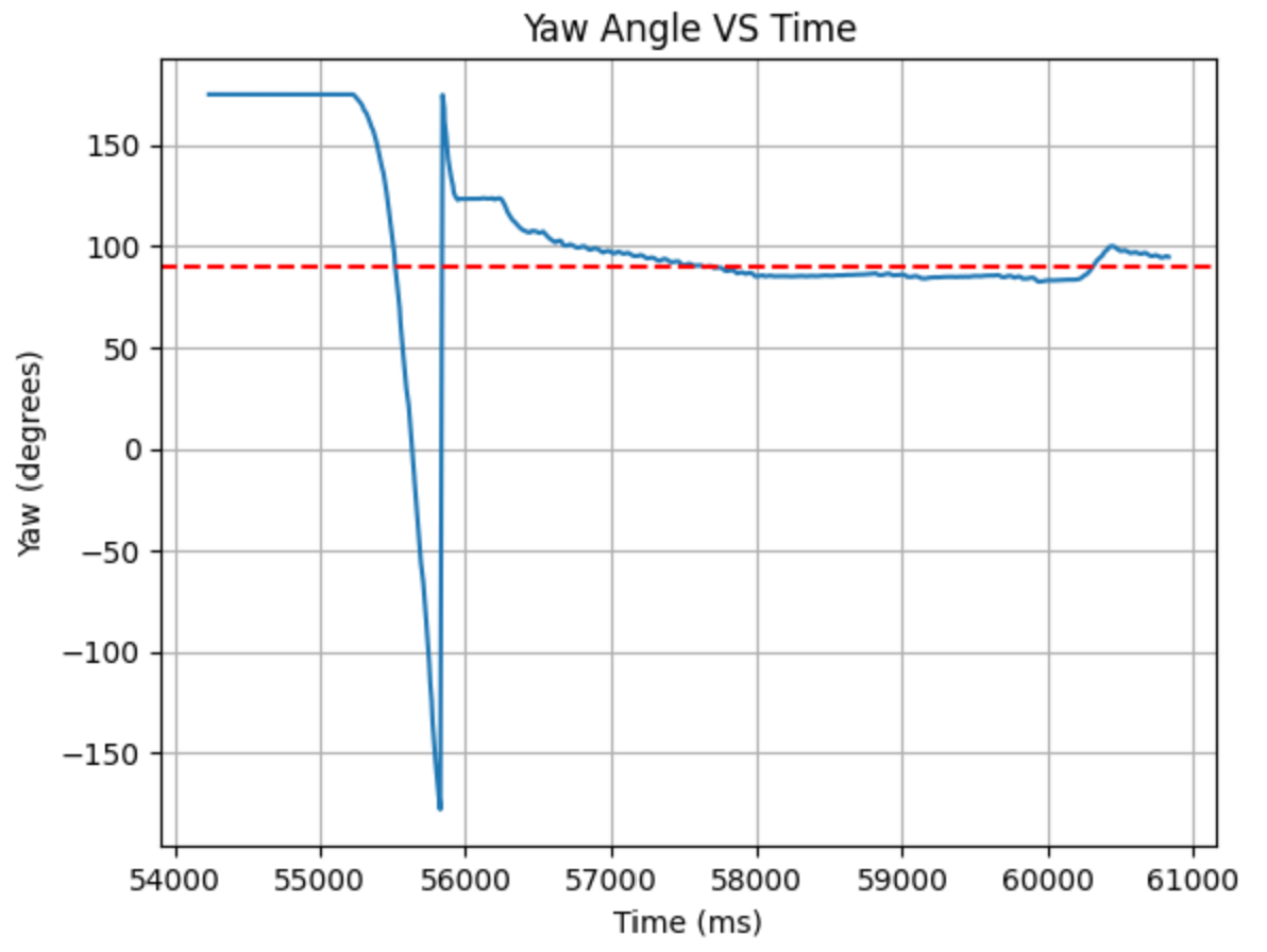
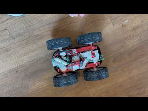
Here is a short demonstration of my car readjusting back to the target angle after interference while running.
Some improvements I want to implement soon: I might tape the wheels to make turning a little easier and with less motor power; speeding up the minor adjustments; stopping the translational motion due to the motor imbalance: after it reaches its target the stronger motor drags the rest of the car and shimmies it forwards.