LAB 9 - MAE4190 FAST ROBOTS
This is lab 9 of fast robots. In this lab, our objective is to map out a static room. To build the map, we will place your robot in a couple of marked locations around the lab, and have it spin around its axis while collecting ToF readings.
Control
I chose to perform this task with a PID orientation control.
I added tape to my wheels as from previous labs it is known that my car has trouble turning and requires a lot of motor power to start the turn. For such a slow speed, precision based turn, I’ll need it to be a smoother motion and ideally not giving the motors a burst of power and sending the car to overshoot.
I want the car to be abel to turn 360 regardless of starting orientation
NEED INITIAL ANGLE OFFSET –> TAKEN WHEN TURN STARTED
/*
        start PID orientation control
        */
        case START_SPIN:

            success = robot_cmd.get_next_value(Kp);
                if(!success)
                    return;
            success = robot_cmd.get_next_value(Kd);
                if(!success)
                    return;
            success = robot_cmd.get_next_value(Ki);
                if(!success)
                    return;

            tindex = 0;
            integral = 0;
            prev_error = 0;
            prev_time = millis();
            prev_sensor_time = millis();
            if (myICM.dataReady())
                {
                    myICM.getAGMT();
                    start_angle = myICM.gyrZ();
                }
            step_turn = 1;
            start_orient = true;

            break;
angle incremented PID control:
                        float rot_angle =  start_angle + step_turn * increment;
                        //angle wrapping
                        rot_angle = fmod(rot_angle, 360);
                        if (rot_angle > 180){
                            rot_angle = rot_angle - 360;
                        }

                        Serial.println(yaw);
                        Serial.println(rot_angle);

                        //PID CALCULATION
                        PID_calculation(yaw, rot_angle, tindex);
                        //motor input
                        if (PID_doc[tindex] < 0){
                            PID_forward(PID_doc[tindex], tindex);
                            Serial.print("PID:");
                            Serial.println(PID_doc[tindex]);
                        } else {
                            PID_backward(PID_doc[tindex], tindex);
                            Serial.print("PID:");
                            Serial.println(PID_doc[tindex]);
                        }
Distance reading from TOF sensor every 25 degree increments:
                            if (abs(error_doc[tindex]) <= 2){
                            control_stop();
                            delay(3000);
                            //take tof sensor reading
                            dist_doc[tindex] = distanceSensor2.getDistance(); //Get the result of the measurement from the sensor
                            Serial.println("dist: ");
                            Serial.print(dist_doc[tindex]);
                            distanceSensor2.clearInterrupt();

                            step_turn += 1;
                            // Reset FIFO
                            success &= (myICM.resetFIFO() == ICM_20948_Stat_Ok);
Debugging: taped up both wheels for less friction error calc due to angle wrapping: added to PID control
    while (curr_error > 180) curr_error -= 360;
    while (curr_error < -180) curr_error += 360;
nan errors –> added constraints for DMP angle calculations
                        double sum = (q1 * q1) + (q2 * q2) + (q3 * q3);
                        if (sum > 1.0){
                            sum = 1.0;
                        }
                        double q0 = sqrt(1.0 - sum);
also this
                // Only delay between readings if no more data is available
                if (myICM.status != ICM_20948_Stat_FIFOMoreDataAvail) {
                    delay(10);
angle wrapping/PID recognition –> sometimes it thinks it’s 180 away (30 to -150 etc)
| ble.send_command(CMD.START_SPIN, “1 | 0.3 | 0.0001”) –> originally 2.2 |
| #Kp | Kd | Ki |
Kp and Kd causing it to spin out –> reduced Kd to 0.1
First try:
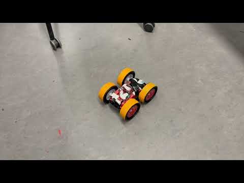
this was on a pretty grippy floor, hence the slow adjustment speed not very on center motor ratio tuned to 1.7
Point turn demonstration:
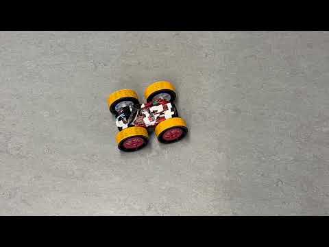
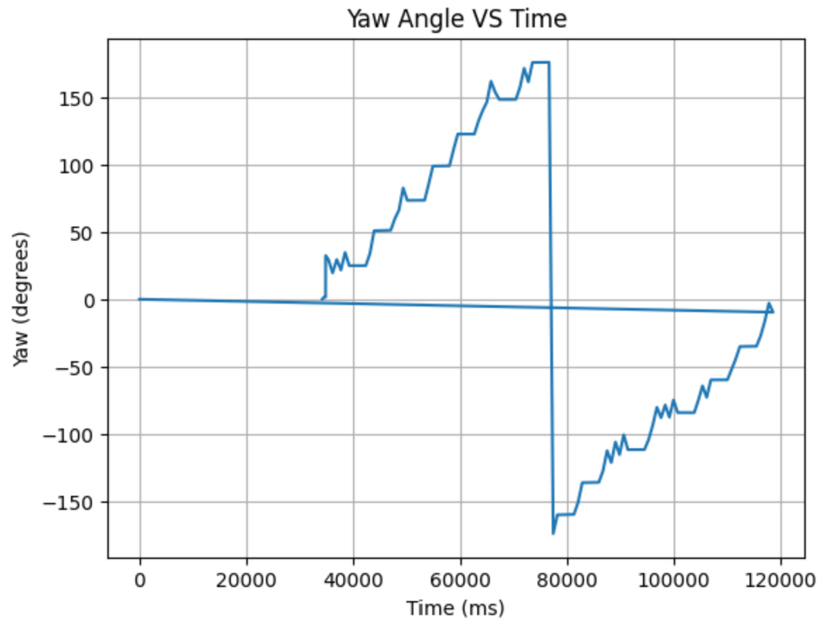

this was done on the lab floors, which were much smoother and more slippery the point turn yaw graphs look like that because the spin was not long enough to fill the full array sent over bluetooth
Here are some videos of my car turning while taking distance data in the map.
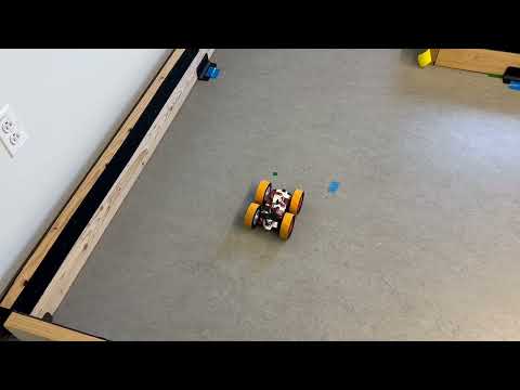
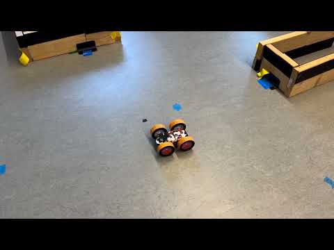
As seen from the videos, the turns still aren’t perfect point turns…the tof distance data will as a result drift and be a little offset from the actual map.
Try rotating twice or more to see how precise your scans are. Not very
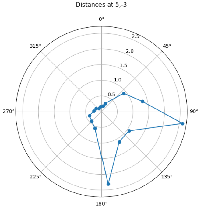
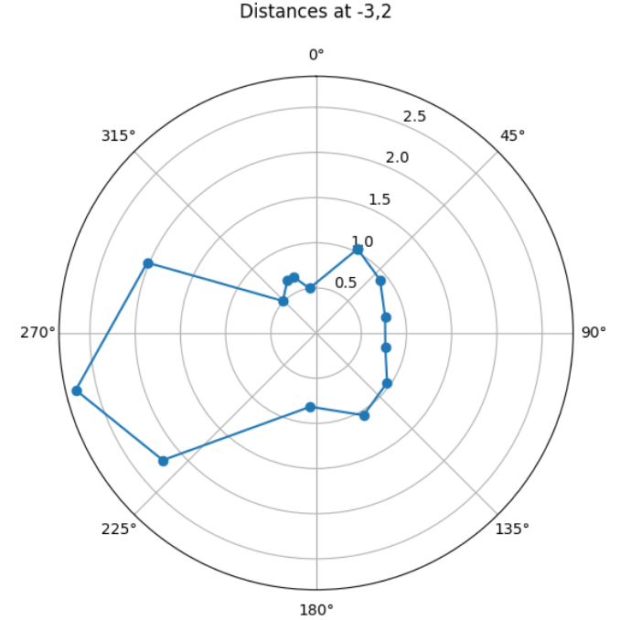
Here are the polar plots for the data points collected:
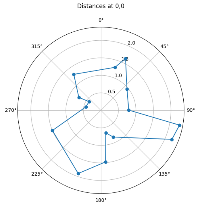
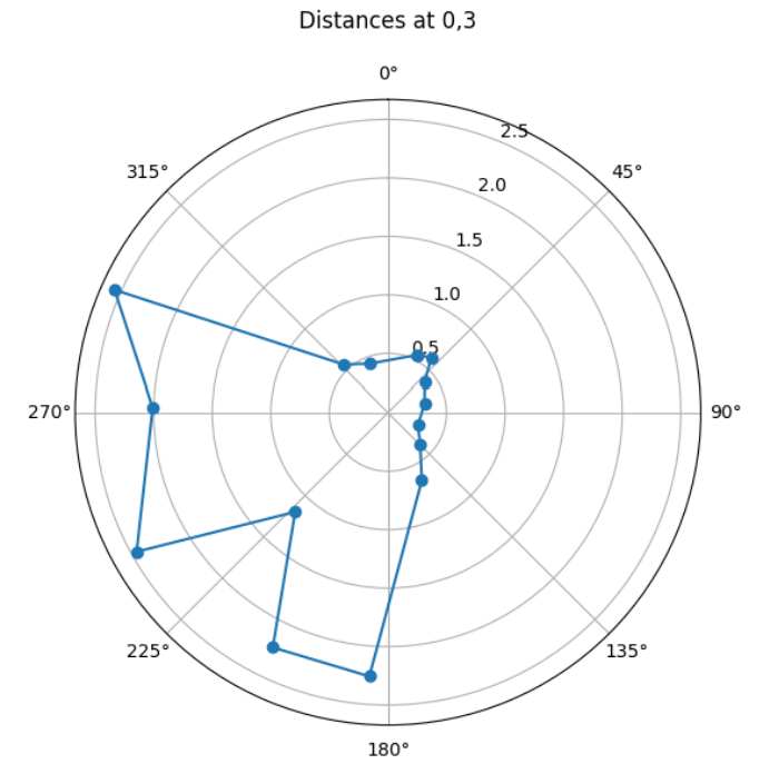
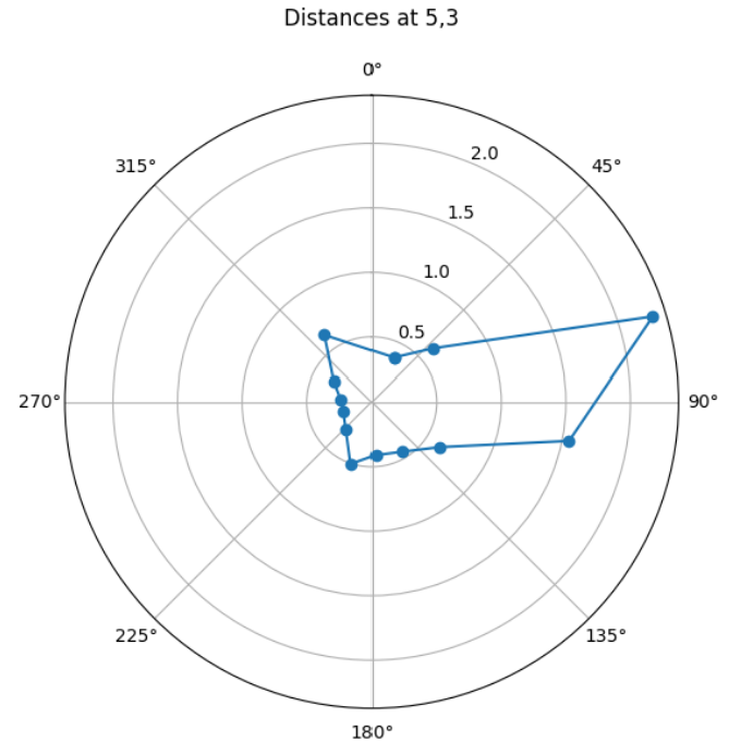
Transformation Matrices
sensor frame to robot frame
\(\begin{aligned} \sigma_1 &= \sqrt{10^2 \cdot \frac{1}{\Delta T}} = 31.6 \\ \sigma_2 &= \sqrt{10^2 \cdot \frac{1}{\Delta T}} = 31.6 \\ \sigma_3 &= 20 \end{aligned}\) [np.cos(alpha),-np.sin(alpha),x], [np.sin(alpha),np.cos(alpha),y], [0,0,1]
robot to world frame
scaling the set coordinates I took the measurements from, changing their units from feet to meters
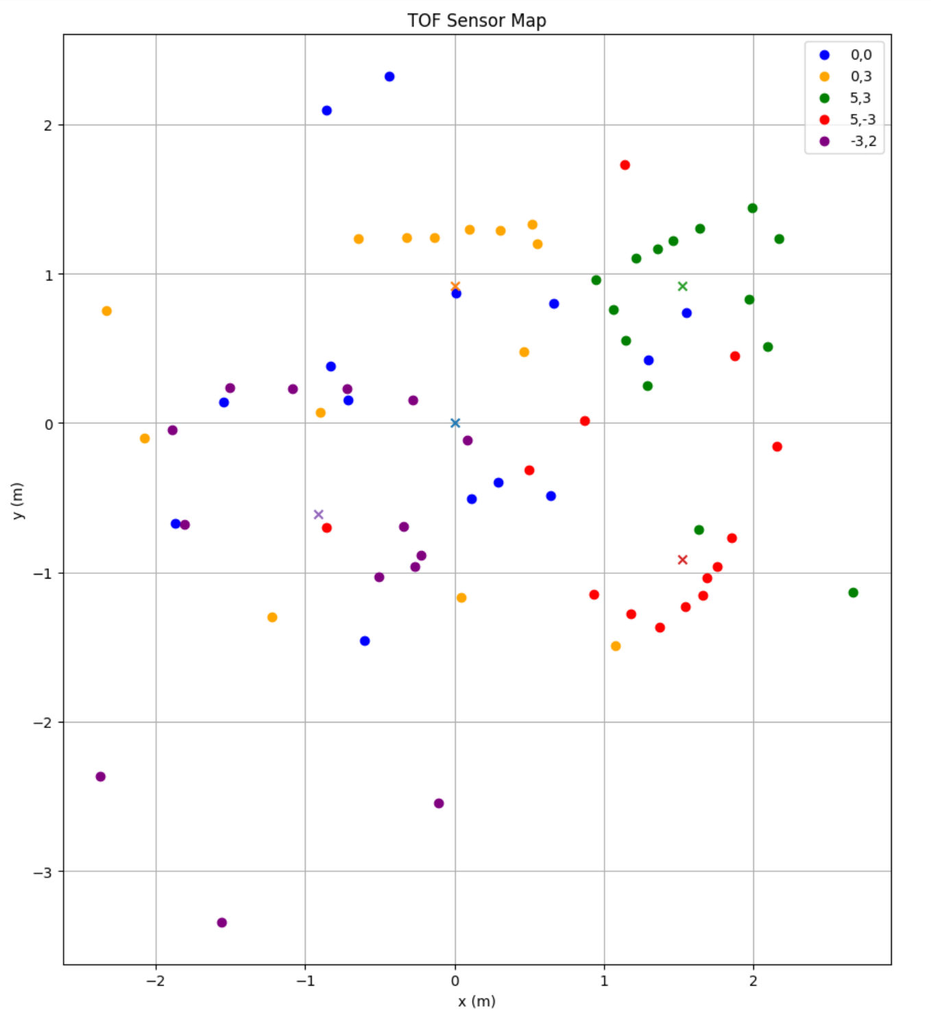
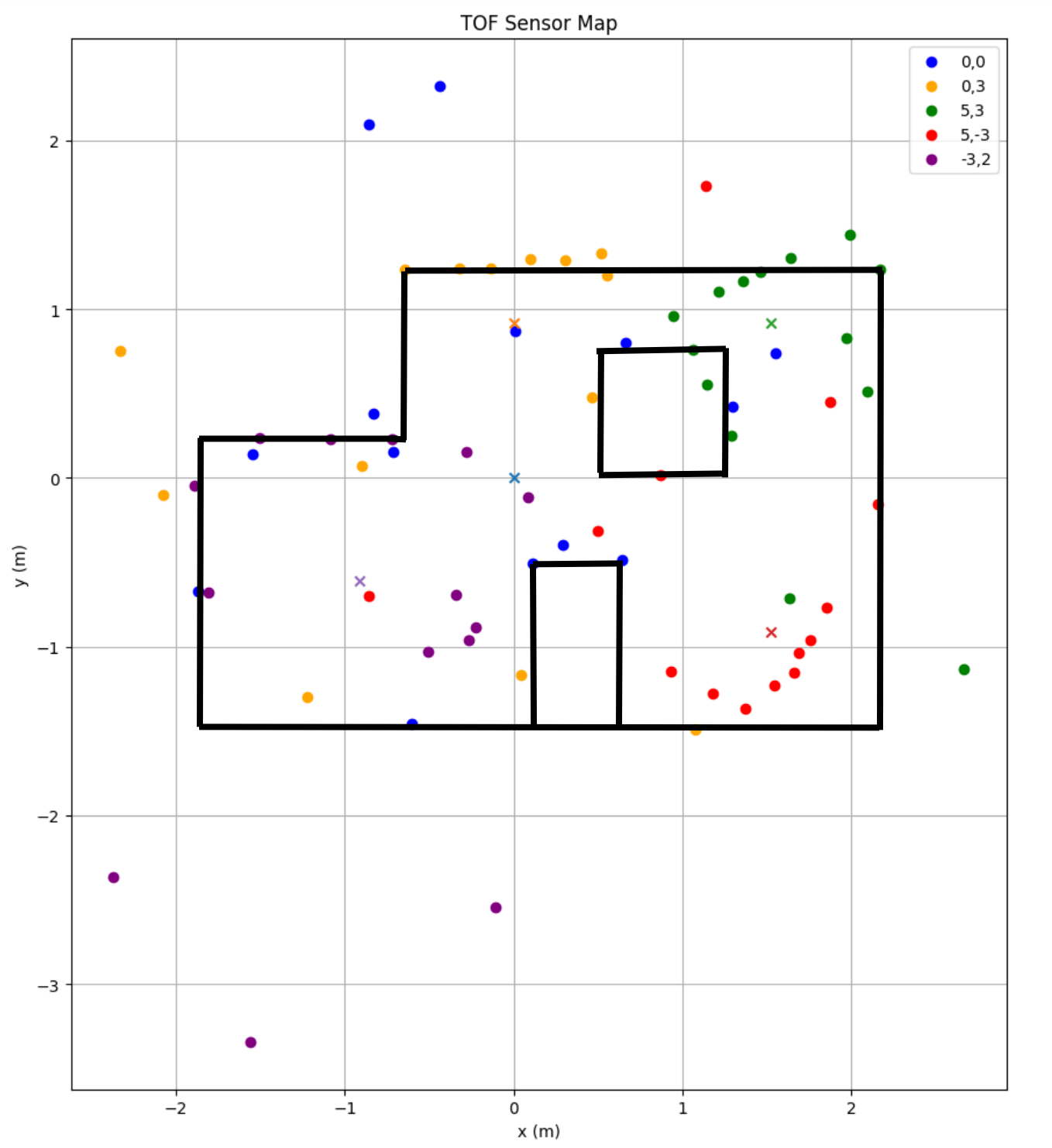
The crosses mark the set coordinates where the readings were taken. The scatter plot looks a little rough. But it does seem to work best in more enclosed spaces (where the car is more in a corner). Aside from the uncertainty from the drift of the car turning, some of the data looks to be skewed possibly due to slight variations in my starting orientation.
Improvements:
- Derivative control spiking in the start (low pass filter with raw gyro data + time step being too small no guard for that)
- starting angles change to offset